A quick background
Before you begin
- Check if you can run WebGL2.
Your browser must be compatible with WebGL2 to continue. - Clone this starter template.
git clone https://github.com/garrison0/raymarching-techniques.git
- Run the starter template.
cd raymarching-techniques
cd starter
npm install
python -m SimpleHTTPServer
This step uses Python to host an HTTP server that serves your project's HTML. If you don't have Python, install it. If you know of another way to host an HTTP server in the command line, feel free to use it.
You can now view the raymarching demo at http://localhost:3000/.
4. Visit http://localhost:3000/ in your browser.
You should see this:
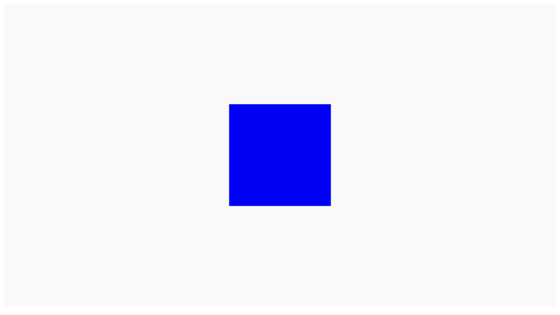
The program renders a box.
The rest of this page briefly explains what's going on in the program.
The WebGL part
Since this tutorial is about raymarching, and not about WebGL, you don't need to know how WebGL works to proceed. In case you're still wondering how everything fits together, this section gives you a high level overview.
index.html
When you visit http://localhost:3000/, your browser displays the index.html file hosted on your Python server. The index.html file includes an HTML canvas. WebGL draws in the canvas.
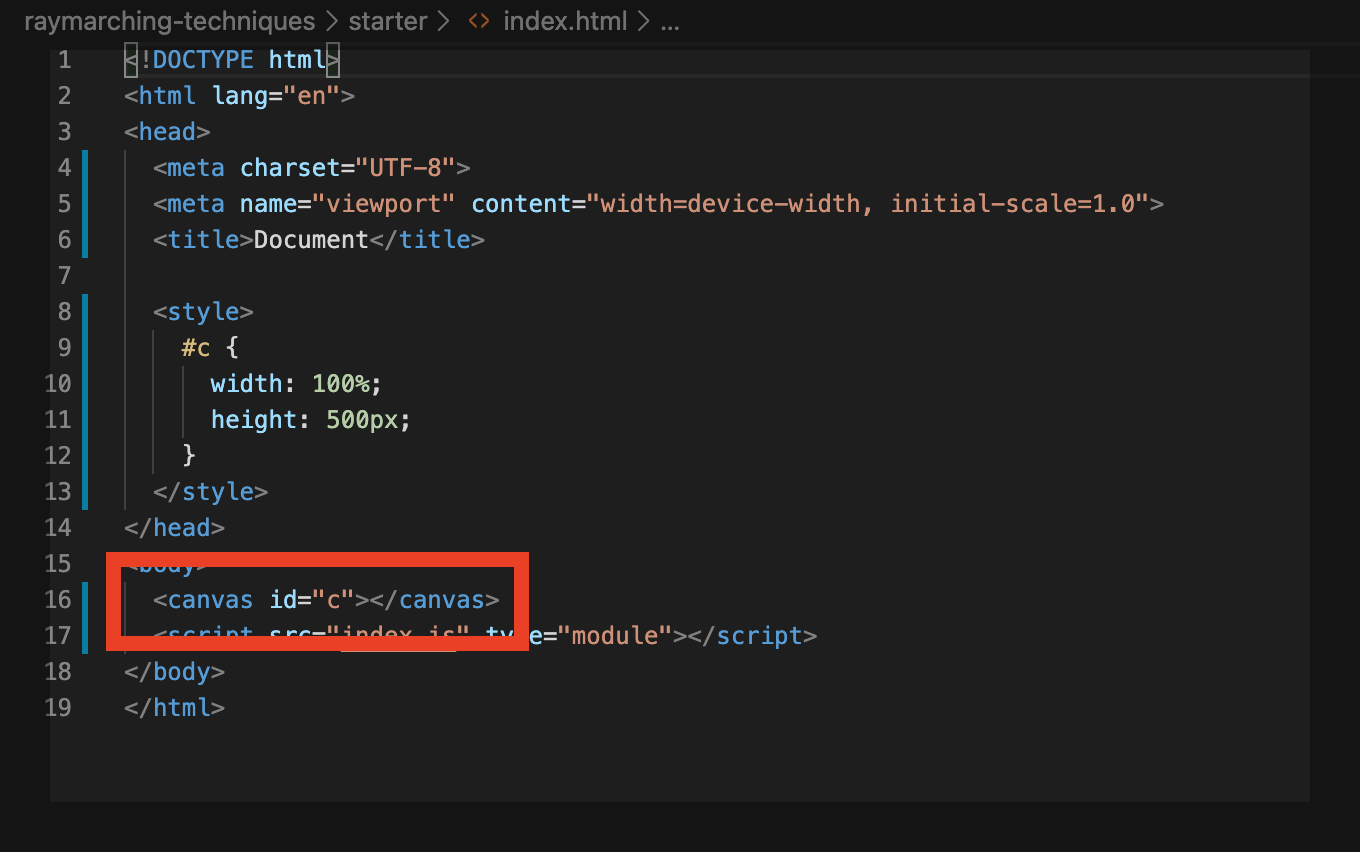
This CSS code styles the canvas. The canvas is wide as the browser window it lives in and 500 pixels tall:
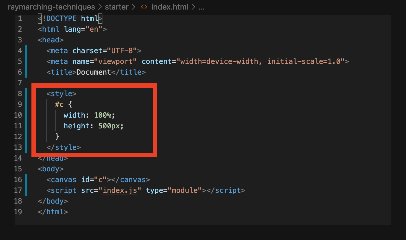
The <script> tag imports and runs the index.js file. index.js contains the JavaScript code used to initialize and run WebGL.
The rest of index.html is boilerplate code. Ignore it for now.
index.js
WebGL is a rendering engine, not a 3D graphics library. It doesn't hold your hand.
Imagine you're in an old airplane cockpit with hundreds of switches and levers. Before take-off, you need to go over a big checklist to set all the switches and levers the way you want them. If something's not set right, you might notice that the airplane isn't behaving the way you expect. Then you have to turn around, land, and go over your checklist all over again.
WebGL feels a bit like that, but instead of switches and levers, WebGL has program state. The various program state options tell WebGL what to do with all the data you give it. WebGL then talks to your GPU to process the data and draw it in the way that you've specified. In case something's not set right, you may only see graphical glitches. Then you have to go back to your code and debug every aspect of your program state.
3D graphics libraries, like Three.JS and Babylon, are built on top of WebGL. They do hold your hand. They hide details from you. They also provide pre-defined materials, light sources, geometries, math helper functions, and so on. The take-away: use Three.JS or Babylon for most production needs. Use WebGL if you want low level control.
Want to know more about WebGL? Check out WebGL Fundamentals.
The WebGL program in index.js draws a rectangle that fills the entire length and width of the canvas. The fragment shader determines what color each pixel in the rectangle should be. Since you can make this pixel whatever color you want, you can do the raymarching within the fragment shader, coloring the pixel according to a raymarched 3D scene.
For simplicity, the starter template uses Tiny WebGL library (TWGL). TWGL spares you from lots of boilerplate WebGL code.
The logic of index.js follows three steps:
-
Fetch the shader files
Because the shader code lives in separate files, you need to fetch these files from your local directory before WebGL can use your code. This guide uses the Fetch API to retrieve the shader code.
// -------- FETCH FILES --------- //
// keys correspond to the file names of each shader
var shaders = {'fs': '', 'vs': ''};
var count = 0;
let numFiles = 2;

for (const key of Object.keys(shaders)) {
  fetch('./shader/' + key + '.glsl')
    .then(response => response.text())
    .then(text => {
      shaders[key] = text;
      count = count + 1;
      if (count >= numFiles)
        init(shaders);
    });
};
You can also write your shader code within <script> tags in index.html.
After fetching the shader code, use it to initialize WebGL.
-
Initialize WebGL
function init(shaders)
{
  state.programInfo = twgl.createProgramInfo(gl, [shaders['vs'], shaders['fs']]);
  state.bufferInfo = twgl.primitives.createXYQuadBufferInfo(gl);
  requestAnimationFrame(render);
}
Initialization is short due to TWGL:
- Pass WebGL the shader code.
state.programInfo = twgl.createProgramInfo(gl, [shaders['vs'], shaders['fs']]);
WebGL uses the combination of the vertex shader ('vs') and the fragment shader ('fs') to construct a WebGL program. WebGL uses this program to draw.
- Call this TWGL helper function to get the data WebGL requires in order to draw a rectangle across the canvas.
state.bufferInfo = twgl.primitives.createXYQuadBufferInfo(gl);
- Enter the render loop.
requestAnimationFrame(render);
requestAnimationFrame(render) tells the browser to call the render function the next time it repaints the page. Since render itself includes a call to requestAnimationFrame(render), the render function loops as long as the browser tab stays open.
-
Render
function render(time) {
  time *= 0.001; // milliseconds to seconds

  twgl.resizeCanvasToDisplaySize(gl.canvas, 1.0);
  gl.viewport(0, 0, gl.canvas.clientWidth, gl.canvas.clientHeight);

  const uniforms = {
    uTime: time,
    uResolution: [gl.canvas.clientWidth, gl.canvas.clientHeight]
  }

  gl.useProgram(state.programInfo.program);
  twgl.setUniforms(state.programInfo, uniforms);
  twgl.setBuffersAndAttributes(gl, state.programInfo, state.bufferInfo);
  twgl.drawBufferInfo(gl, state.bufferInfo);

  requestAnimationFrame(render);
}
The browser performs this sequence during each iteration of the render loop:
- Resize the canvas, in case the browser window has resized.
twgl.resizeCanvasToDisplaySize(gl.canvas, 1.0);
gl.viewport(0, 0, gl.canvas.clientWidth, gl.canvas.clientHeight);
- Set the uniforms.
const uniforms = {
  uTime: time,
  uResolution: [gl.canvas.clientWidth, gl.canvas.clientHeight]
}
...
twgl.setUniforms(state.programInfo, uniforms);
Using WebGL uniforms, you can pass data from JavaScript to our shader code. In particular, the code passes the time and the size of the canvas.
- Tell WebGL to use the WebGL program containing our shader code and to use the data needed to draw a rectangle.
gl.useProgram(state.programInfo.program);
...
twgl.setBuffersAndAttributes(gl, state.programInfo, state.bufferInfo);
- Draw the rectangle, which is the next frame of our raymarching animation.
twgl.drawBufferInfo(gl, state.bufferInfo);
The raymarching part
The raymarching code lives in the fragment shader at shader/fs.glsl. The fragment shader determines what color to draw each pixel in the rectangle as.
Like a C program, the entry point of the fragment shader is the main function.
The fragment shader performs the following steps for each pixel:
- Find the direction of the ray to cast
- March the ray in that direction until an intersection is found or until the loop reaches the maximum number of iterations
- Determine the color to render using the intersection data to perform lighting calculations
The next section looks at each step in more detail.
Feeling lost? Check out the resources listed in the introduction!
Find the direction of the ray to cast
in vec2 vUv;
...

mat3 setCamera( in vec3 ro, in vec3 ta, float cr )
{
  vec3 cw = normalize(ta-ro);
  vec3 cp = vec3(sin(cr), cos(cr),0.0);
  vec3 cu = normalize( cross(cw,cp) );
  vec3 cv =          ( cross(cu,cw) );
  return mat3( cu, cv, cw );
}

void main() {
  // camera ray origin
  vec3 ro = vec3( 0.0, 0.0, 1.0);
  // camera target
  vec3 ta = vec3( 0.0, 0.0, 0.0);

  mat3 ca = setCamera(ro, ta, 0.0);
  float aspect = uResolution.x / uResolution.y;
  vec2 p = vec2(aspect, 1.0) * (vUv - vec2(0.5));

  // ray direction
  vec3 rd = ca * normalize( vec3(p, 5.0) );
}
By convention, the GLSL community uses two-to-three letter variable names. Keeping the variable names short makes the math easier to read.
Here are some common abbreviations:
ro= ray originrd= ray directionca= camerata= target (where the camera is pointing)uv= texture coordinates
Texture coordinates are also sometimes called UV coordinates.
This guide also uses these abbreviations in the math below.
By yet another convention, the GLSL community puts a 'u' in front of WebGL uniforms and a 'v' in front of WebGL varyings.
See how this affects the variable names at the beginning of the fragment shader:
in vec2 vUv;
uniform vec2 uResolution;
uniform float uTime;
uvvUvresolutionuResolutiontimeuTime
Recall that ray casting consists of shooting rays through an imaginary grid in front of a camera into a scene filled with objects:

Suppose the camera lives at the origin and the camera is "looking" in the direction of the z axis:
How can you find each ray's direction from this information? In other words, what pixel in the image grid is each ray pointing at?

You can get to the center of the image grid by following along the direction the camera is "looking" at. Call this direction the vector, defined by :

Get , the vector pointing from to , by calculating .
Though the diagrams display and as points, they're actually vectors.
What you need are the and vectors of the image grid:

You also need some way of telling how far and how far you should go for each pixel. Then, just like locating a position within 2d Cartesian coordinates, you could locate each ray's position within the image grid:
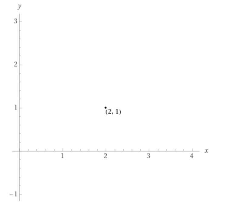

In this case, you're in luck. Since the camera is looking straight ahead, the camera is axis aligned. You can use the axis as your vector, and you can use the other two axes, and --
--as and to locate your ray on the image grid.
Remember how WebGL is actually drawing a full screen rectangle? You can use this rectangle's texture coordinates uv to locate your position within the canvas. This, in turn, tells you how far "Right" and how far "Up" each ray needs to go in the image grid.
Texture coordinates are interpolated values that tell each pixel its relative position within a rendered geometry. They're typically used for adding textures, hence the name.
For more details on WebGL textures, read the WebGL fundamentals guide.
The ray direction is then:
This equation determines each ray's position in the image grid. Since the camera is axis aligned, this simplifies to:
What about in general? How can you generate a ray direction for each pixel given any vector?
The equation that determines the ray direction is the same, but you need some way of figuring out the and vectors. Here are the steps:
- By the definition of the target vector, is always :

- Choose the axis as a temporary :

You could choose any direction as . Choose the axis for convenience. Choosing the axis matches the math to what you see. Barring any rotations, shapes appear axis-aligned--nice and straight.
- Use the cross product to find :

By the definition of the cross product, is perpendicular to both and .
- Use the vector to find the true vector that's perpendicular to both and :

Now repeat the math with the UV coordinates:
For simplicity, you can represent this operation using a matrix:
Expand the math and it looks exactly the same:
Rotate the camera about the axis
mat3 setCamera( in vec3 ro, in vec3 ta, float cr )
{
  vec3 cw = normalize(ta-ro);
  vec3 cp = vec3(sin(cr), cos(cr),0.0);
  vec3 cu = normalize( cross(cw,cp) );
  vec3 cv =          ( cross(cu,cw) );
  return mat3( cu, cv, cw );
}
The setCamera function builds the matrix which contains the , , and vectors.
cr represents the camera rotation angle. Instead of choosing the axis as the temporary vector, choose cp, a rotated vector, based on cr:
vec3 cp = vec3(sin(cr), cos(cr),0.0);
Since the vector is obtained by taking the cross product of and cp, the rotated vector, you're essentially rotating the image grid around the vector.
Set cr in main to cos(uTime) and view your program:
mat3 ca = setCamera(ro, ta, cos(uTime));
Notice how the and vectors are rotating around the " vector, making it look like the box itself is rotating.
Zoom in and out
vec3 rd = ca * normalize( vec3(p, 5.0*abs(cos(uTime)) ) );
The 5.0 in vec3(p, 5.0) is like a zoom.
Recall the definition of rd:
What would happen if you multipled by some constant , pushing the image grid further away from the camera?

The visual field gets smaller. Since the camera position, , stays the same, all you're doing is decreasing variation along the and " directions across all of the rays. The effect: more rays being focused around the direction. Since each ray corresponds with a pixel on the screen, this looks like zooming in.
Set 5.0 to 5.0 * abs(cos(uTime)) and view your program:
vec3 rd = ca * normalize( vec3(p, 5.0*abs(cos(uTime)) ) );
As gets closer to , the image grid gets closer to the camera, zooming out. Likewise, when gets closer to , the image grid gets farther from the camera, zooming in.
March the ray
vec2 raycast (in vec3 ro, in vec3 rd, float time)
{
  vec2 res = vec2(-1.0,-1.0);

  float tmin = 0.001;
  float tmax = 100.0;

  float eps = 0.0015;
  float t = tmin;
  for( int i = 0; i < 228 && t < tmax; i++) {
    vec2 h = map( ro + rd*t, time );

    if( abs(h.x) < eps){
      res = vec2(t, h.y);
      break;
    }

    t += h.x;
  }

  return res;
}
To perform an iteration of the ray marcher:
- Find the minimum distance to any object in the scene
vec2 h = map( ro + rd*t, time );
- Exit the loop if the minimum distance is below a threshold,
if( abs(h.x) < eps){
  res = vec2(t, h.y);
  break;
}
Being below the threshold indicates that the ray has hit an object. 3. Else, step the ray by the minimum distance. Distance functions are blind to direction. Since the map function doesn't tell you the direction of any of the scene's objects, you can't step by more the minimum distance each iteration.
Here's an example:

Even though the closest object is behind the ray direction, the ray marcher has to step by the minimum distance during this iteration.
Map
vec2 map (vec3 p, float time)
{
  vec2 res = vec2(1e10, 0.0);
  p = p + vec3(0.0, 0.0, 15.0);
  res = vec2(sdRoundBox(p, vec3(0.5), 0.0), 15.0);
  return res;
}
Map chains together a bunch of SDFs, returning the minimum distance. In this case, map contains the SDF for the box.
Notice how the result res is a vec2. For convenience, stick the material ID of the nearest object in res.y. raycast returns the material ID in case it detects an intersection and then render uses the material ID to determine the pixel color.
Signed distance functions (SDFs)
float sdRoundBox( vec3 p, vec3 b, float r )
{
  vec3 q = abs(p) - b;
  return length(max(q,0.0)) + min(max(q.x,max(q.y,q.z)),0.0) - r;
}
SDFs are functions that return the minimum distance to some primitive shape. You can create more complicated shapes by combining these "primitives" together in a process called "modeling."
Watch this video to see how to derive the SDF of a box.
Determine the color
vec3 render(in vec3 ro, in vec3 rd, float time)
{
  vec3 col = vec3(0.95);

  vec2 res = raycast(ro,rd, time);
  float t = res.x;
  float m = res.y;

  vec3 pos = ro + rd*t;

  // lighting
  if ( m > 5.0 ) {
    vec3 nor = calcNormal(pos, time);
    col = nor;
  }

  return vec3( clamp(col, 0.0, 1.0) );
}
Once the raycaster detects an intersection, return the material ID m of the object intersected with.
Use this material ID in the render function. render needs to know the material properties of the object (shininess, color, and so on) to determine the color of the pixel during lighting calculations.
For testing purposes, you can avoid the issue and set the color to the normal vector:
vec3 nor = calcNormal(pos, time);
col = nor;
Find the normal
vec3 calcNormal( in vec3 p, float time )
{
  const float eps = 0.0001;
  const vec2 h = vec2(eps,0);
  return normalize( vec3(map(p+h.xyy, time).x - map(p-h.xyy, time).x,
                         map(p+h.yxy, time).x - map(p-h.yxy, time).x,
                         map(p+h.yyx, time).x - map(p-h.yyx, time).x ) );
}
calcNormal finds the normal direction of the nearest object surface by the method of central differences. Recall the formal definition of the derivative from Calculus:
You can approximate the derivative by taking small values of .
It works in three dimensions, too. Conveniently, mathematicians have defined the derivative to be in the direction of the normal vector. Amazing.
The code swaps for and approximates the derivative along each direction. Given , is GLSL shorthand for . Likewise for the other axes:
return normalize( vec3(map(p+h.xyy, time).x - map(p-h.xyy, time).x,
                       map(p+h.yxy, time).x - map(p-h.yxy, time).x,
                       map(p+h.yyx, time).x - map(p-h.yyx, time).x ) );
You don't need to divide by because you're normalizing the vector. Remember, you don't actually care about the magnitude of the derivative, you're just using it to find the direction of the normal vector.
All done. But this starter template is simple--you can only see one side of the box. The rest of the documentation will teach you all of the techniques needed to get to the final result.